Plumbing Coolant Hoses
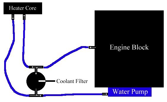
Please excuse the crudeness of this diagram, but this is the basic method that I chose to plumb my coolant filter into my cooling system. Every coolant filter setup I have ever seen was plumbed into the coolant lines going to the heater core; this is a simple and effective method of tying into the cooling system. Note that the coolant filter is plumbed in as a bypass filter setup. To my knowledge, every coolant filter sold is meant to be installed as a bypass filter. I was lucky in that I had already drained the cooling system in order to replace the radiator, so I didn't need to lose any coolant in order to perform this installation. If I hadn't, I would have needed to at least partially drain the system. I was also using this chance to clean out the cooling system as much as possible (an easy task since I had recently cleaned it out as part of my head gasket project the previous summer) and convert to running 100% Caterpillar Extended-Life Coolant.
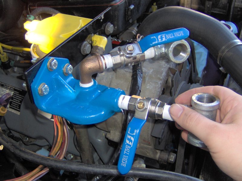
One important addition here is the installation of valves on both sides of the coolant filter. With these valves, I can isolate the coolant filter from the rest of the system. This allows me to change out the filter without draining the system, and also to be able to keep from losing coolant if the filter itself ever fails for whatever reason.
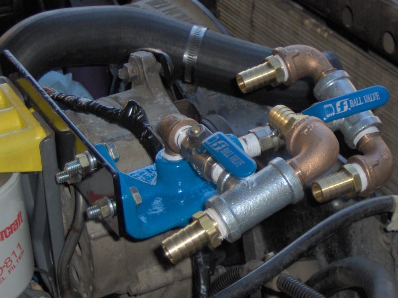
The "manifold" completed. It looks more complicated than it is. I decided to make use of elbows to minimize the number of turns the hoses will need to make, helping to make them shorter as well as minimizing the chances of kinking any of the hoses. All the fittings pictured are marine-grade fittings acquired from West Marine. Note that I used teflon tape for the fittings. I found out shortly thereafter that Caterpillar ELC will eat teflon tape! I have minor leaks from all of these fittings now. I decided that the leaks are too minor to justify partially draining the system and disassembling the "manifold" in order to remove the teflon tape and use a liquid sealant instead. If I do any other cooling system work that requires draining it, I'll remedy this at that time...until then, I would suggest that others use a liquid sealant instead of teflon tape when working on a cooling system that will see an ELC. Also, just for reference, the heater hoses on a Ford truck are standard 5/8" inside diameter hoses.
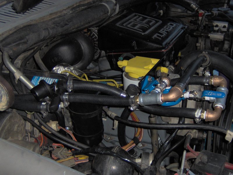
The completed project. Note the Prestone flush T-fitting added, along with the heater core bypass valve (described in a different section). Other than the hose going to the water pump (that has to curve over the alternator) and the hose coming up from the cylinder head, the hose runs were pretty straight. I deliberately left a little bit of slack in the hose with the Prestone T-fitting in it, so that I could bring the T-fitting up to be the highest point in the cooling system to (hopefully) allow for somewhat better air escape when trying to bleed the system, and leave it out of the way for normal use.
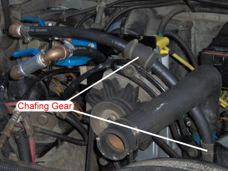
I noticed two points where the hose going to the water pump was making contact with the engine. So, following a habit I learned working on boats, I took a piece of rubber hose, cut it lengthwise, fitted it over the good hose in the location where it was contacting the engine, and zip-tied it in place. This is to keep the hose from chafing on the engine parts (the alternator above, and the alternator bracket below). I still need to keep an eye on the chafing gear; if it starts to wear through, the hose can still be eaten away. That said, it's far easier to replace the chafing gear than it is to replace the hose.
Making and Installing Filter Head Bracket
Painting and Installing the Bracket and Filter Head
Plumbing Coolant Hoses
Back to main Ford page
Page updated November 13th, 2005

Page best viewed with Mozilla FireFox.